
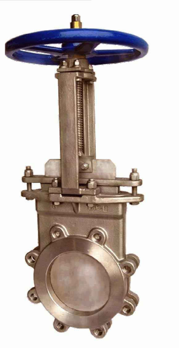
 Cast Body Resilient Seat Knife Gate Valve
Cast Body Resilient Seat Knife Gate Valve
Features and Benefits
Resilient seat gate valve with cast stainless steel body, gate, packing gland, and yoke.
Solid one piece cast body in corrosion resistant stainless steel.
Compact wafer configuration to Tappi and MSS standard face to face.
Replaceable resilient seat.
DRIP TIGHT SHUT OFF.
Designed to handle dense mixtures of stock and slurries.
Variety of resilient seat material available.
Smooth flow–non-clogging FULL PORT design.
Positive SHUT OFF in BOTH DIRECTIONS.
Bonnetless, outside screw and yoke, non-rising handwheel, rising stem.
Available in sizes from 2″ to 24″ diameter.
Meets Tappi standard TIS 405-8 and MSS SP-81 for stainless steel bonnetless, flanged, wafer knife gate valves.
150 PSI working pressure.
Flanges match ANSI B16.5-150 lbs. standard with all tapped holes and serrated raised gasket faces.
DIMENSIONS (INCHES) AND WEIGHTS

DESCRIPTION:
The Cast Body Resilient Seat Knife Gate Valve is a bonnetless knife gate valve. It has a rubber seat that seals on the perimeter of the gate. It is a bi-directional valve, meaning that it can be installed in either direction. Multiple rows of packing are used to seal between the gate and the body. The pressure rating of the 3" through 24" Cast Body Resilient Seat Knife Gate Valve valves is 150 PSI CWP(Cold working pressure). The Cast Body Resilient Seat Knife Gate Valve has a stainless st `eel body and gate.
INSTALLATION:
Since the Cast Body Resilient Seat Knife Gate Valve is a bi-directional valve it is not necessary to determine an upstream or downstream side of the valve. It can be installed either way in the pipeline. Install the valve to the mating pipe flange using proper size bolts. See Chart 1 for bolt size. Bolt length is not included on Chart 1 since different flanges will require different length bolts. It is very important to choose the proper length of bolt for the bolt holes in the chest of the valve (if possible use studs). These holes are bottom drilled and tapped holes and in some cases contain less than a bolt diameter of threads. Be careful not to bottom out bolts in the chest during installation. If necessary use washers to shorten the penetration of the bolt into the chest holes. Chart 2 gives recommended bolt torques to be used during installation, however, depending on the type of gaskets being used the required torques may be higher or lower. Use the cross torque pattern method for tightening the bolts. Mating flanges must be parallel and true with each other and the valve. Do not use the valve to pull together or force apart the two mating pipes. After installation, open and close the valve once to assure smooth operation.SHIPPING & STORAGE:
For shipment, the valve will be in the closed position. Small valves (3", 4", and 6") may be shipped in individual boxes. Larger valves and large quantities will be shipped on pallets, skids or in boxes, all of which will require a forklift for moving. Storage should be in a clean dry environment such as a warehouse.
MAINTENANCE:
The only items requiring maintenance on the cast body resilient seat knife gate valve are the packing, the seat and the lubrication of the stem. The packing gland may require adjustment after installation, especially if the valve has been in storage for a long time. When adjusting packing on valves with four or more bolts it is best to tighten the bolts evenly on both sides of the packing gland using the cross torque method. Normally just a small amount of tightening per bolt is required. Do not tighten the bolts more than is necessary to stop the leaks. Try to adjust the packing gland down evenly to avoid the possibility of the gland rubbing on the gate as it moves. Generally, the more a valve is operated the more maintenance will be required to keep packing leaks under control. To replace a seat see page 3, 2LBin SEAT REPLACEMENT PROCEDURE. Lubricate the stem nut and stem by using a grease gun on the grease fitting at the top of the yoke.
2LBin SEAT REPALCEMENT PROCEDURE:
1) To replace a seat first remove the valve from the line.
2) Disconnect the stem clevis from the gate and remove the yoke and stem assembly. Remove
the packing gland, packing and valve gate.
3) To remove the seat it will probably take a good firm grip on the seat and the metal wire insert with a pair of vice grips and possibly have the aid of a come-along to pull the old seat from the valve body. In the bottom of the valve, the seat groove has retainer ledges and the rubber seat must be pulled through this narrow opening.
4) To install the new seat and repack the valve the opposite procedure is required. First, place the new seat into the valve body seat cavity by bending the seat into a horseshoe shape and insert it into the seat cavity. Take a three or four-foot length of flat bar approximately 3/8" x 2" or 3" wide and tamp the seat as firmly as possible into the bottom of the valve and along the sides.
5) When the seat is in place with the ends on each side protruding above the packing box, insert the valve gate. Install the yoke and stem assembly and move the gate to its bottom position, ensuring that the seat is pushed into its retainer groove all around the bottom and along the sides.
6) When the seat is definitely in place, remove the yoke and stem assembly. Repack the
valve, placing packing strips on each side of the gate for the full length of the packing box.
Make sure that the packing is cut long enough and fits firmly against each end of the packing
box. When the valve gland is packed to its fullest, take a hacksaw and cut off the excess
rubber seat that extends above the packing box on each side.
7) Install the packing gland and reinstall the yoke and stem assembly.
8) Stroke valve through one full cycle and assure easy operation and that there is no rubbing
of the body or packing gland on the gate.
9) Under pressure tighten the packing gland bolts only enough to stop packing leakage.